
Boat speed calibration is a fundamental task for the race navigator. Accurate and consistent measurement of a boat’s speed through the water (STW) is vital for yacht racing. This measurement helps the instrument’s CPU calculate key metrics we rely on, including:
We apply it to the apparent wind (AW) to determine the true wind angle and speed (TWA & TWS), which in turn affects the calculation of true wind direction (TWD).
We also use it to calculate the current by comparing the boat’s motion through water (MTW) to GPS motion over ground (MOG).
We use the TWA and TWS to extract target data from the boat’s polar curves. Using incorrect TWA and TWS leads to inaccurate targets. You then compare the incorrect actual and target STW!
Using the wrong STW throws off your wind, current, and performance readings.
Boat speed sensor
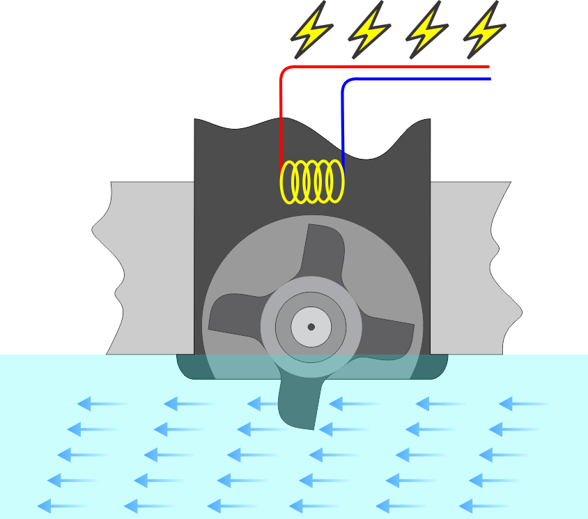
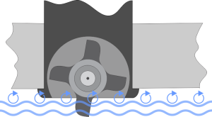
Measuring the STW begins with the water speed sensor, typically a paddle wheel that spins as water passes under the boat. This sensor sends electrical pulses to the instrument’s CPU as the wheel turns, with faster speeds producing higher pulse frequencies and slower speeds producing lower frequencies.
Each paddle is magnetized, and as it moves past the electronics inside the housing, it creates a pulse.
Essentially, there’s a direct correlation between the boat’s speed and the frequency at which these pulses are generated.
Boat speed sensor calibration
Pulse frequency is measured in Hertz, and boat speed is measured in knots.
To convert the sensor’s pulse frequency into boat speed, you need to find a conversion factor in Hertz per knot (Hz/Kt) specific to your boat. Modern instruments use a percentage correction to the boat speed after the CPU calculates it internally based on a fixed preset Hz/Kt value, which makes calibration easier.
Calibrating appears simple; it involves finding the right Hz/Kt or percentage to ensure the instruments accurately convert pulses into boat speed.
We refer to the speed at which you calibrate the sensor, typically around 6 or 7 knots, as your baseline calibration speed.
The devil is in the details!
Unfortunately, a single constant number isn’t enough for good all-around calibration. Several factors influence the simple calibration described above. Some are due to incorrect sensor installation, while natural phenomena cause others.
Sensor placement
Poorly positioned sensors generate inconsistent and asymmetrical readings. The proper way to install the through-hull housing for the sensor is:
- Install it as close to the centerline as possible; otherwise, readings from each tack will differ.
- Keep it clear of the front edge of the keel; otherwise, the water flow in that area may distort the readings.
- Install it away from the bow’s waterline because bubbles can cause inconsistent readings.
Good installers follow the best practice of placing the sensor two-thirds of the way from the bow to the keel line. A specific case involves V-shaped hulls, which may require a sensor on each side along with additional calibration for each one.
Sensor alignment
If the sensor does not align perfectly with the centerline, and because water flows slightly laterally due to the boat’s leeway, the paddle wheel will spin at different rates during opposite tacks.
The person installing the instruments should carefully manage the through-hull alignment, just like sensor placement.
Linearity (Heel Correction Table)
The paddle wheel is located in the boundary layer between the hull and the flowing water. This layer contains microturbulence, which slows water near the hull’s surface and immediately affects the paddle wheel’s rotation.
The main issue is that this effect becomes more noticeable the slower you sail and decreases as you go faster. It’s a fluid dynamics phenomenon, not a sensor problem.
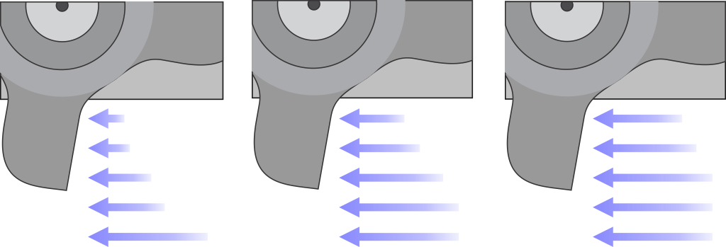
Let’s assume your instruments are perfectly calibrated at a baseline speed of 6 knots. If you’re sailing slower, for example, if the displays show a speed through water of 3 knots, your actual STW will be about 15% higher. Conversely, if you’re sailing faster, with displays showing 10 knots, your actual STW will be around 10% lower. In other words, sensor calibration is not linear
The solution is to include an extra adjustment to the already calibrated STW when sailing at different speeds.
If you use instruments with a B&G processor, you’ll find a table for STW adjustments, including for heel angle corrections. For the legacy H3000 system, it’s called the “Speed Linearity Correction Table.” On newer H5000 and Hercules processors, it’s the “Heel Correction Table.”
When used as a standalone processor, EVOLUTION also provides an STW linearity correction table.
Finding the values to enter into these tables takes considerable effort. This Excel sheet provides approximate values for 0º, 10º, and 20º heel angles based on your baseline calibration speed.
Biological growth on the hull and sensor
Those tiny marine critters really love boats!
After you clean your boat for a race, algae and crustacean larvae will quickly attach to the hull and begin to grow. Within just a few days, even though they’re still small, they’ll be large enough to affect the turbulence on the water-hull boundary and skew your calibration value.
This answers the eternal question: When should I calibrate my speed sensor? As often as possible! Ideally, calibrate before a race, a training session, or a trial. Between races, don’t let a week go by without calibrating.
When not in use, you can remove the sensor to prevent fouling. Repositioning it in the through-hull again will never be precisely at the same level, so recalibration will be necessary.
Preparing for the boat speed calibration
EVOLUTION provides a calibration tool that lets you quickly and easily calibrate your speed sensor. Calibration varies depending on the type of instrumentation used. Nevertheless, please review the next section for details. Always follow the routine below before calibrating.
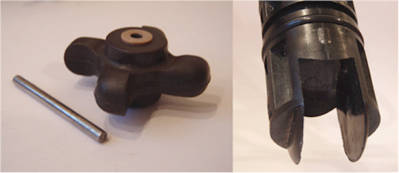
- Ensure the sensor is thoroughly clean, free from dirt and marine growth. If necessary, disassemble the unit and clean the paddle wheel, axle, and housing.
- When reassembling the unit, ensure that the paddle wheel is positioned to face the direction of the water flow.
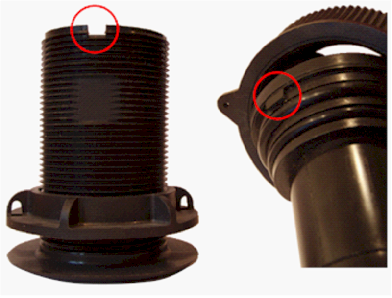
- When reinserting the sensor, ensure the alignment notch fits securely into the through-hull groove and that you lower the sensor as far as possible into its correct position.
Practical tips
- Use plain bleach and a small toothbrush to thoroughly clean the underwater part of the sensor and also eliminate algae and larvae.
- Do not use lubricant on any part of the sensor. The lubricant will wash away quickly, leading to inaccurate calibration.
- Ensure that the sensor is structurally sound. The lateral fins may have been twisted when hitting an underwater object or were crushed by the crane’s slings.
- Keep the bottom of the boat clean, at least in front of the sensor hull pass-through, thus minimizing turbulence that can affect the speed of the water over the sensor paddle wheel.
Resources
Below, you will find links to technical notes explaining how to use the EVOLUTION boat speed calibration tool specific to your instruments. It is also helpful if you can review the operations manual for these instruments and check the calibration section, as you may need to review or input specific values.